Retired

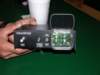
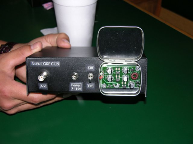
Image of prototype board/assembly
The following are photos of serial number 1:
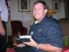
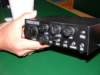
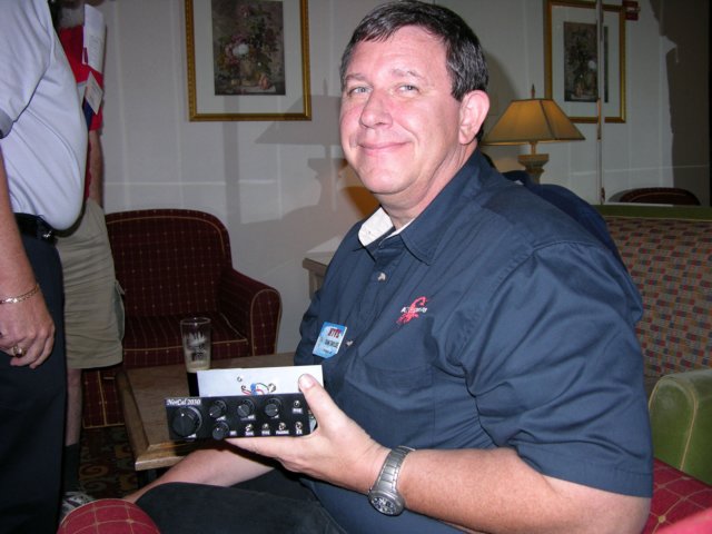
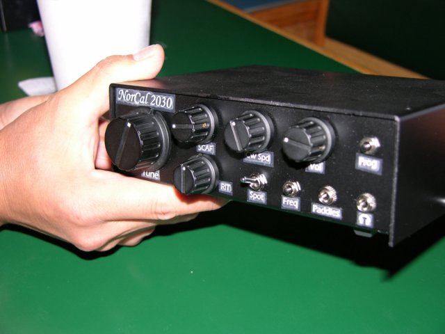
Gallery of built units
November 11, There was a problem with the cases that we ordered for the NC2030. The
case is predrilled, and solder masked. Due to a file mixup, there was a
mistake on the solder mask and a hole location. We called the fine folks
at Ten Tec who are doing our cases and when we told them about the
problem, they insisted on doing the right thing and redoing the cases at
their expense. They will be making all of the bottom parts of the case
over again. Ten Tec said that they want to do everything that they can to
make sure that the cases are right, and so do we. This will delay
shipping until Dec. 2. We have all other parts here, and 8 of the 10
surface mount bags are done. Hopefully we can finish the last 2 bags of
surface mount parts tomorrow. Then we will have to do the wire bag, loose
parts bag, and then all that we will be waiting for will be the cases.
We want to thank all of you for your patience and understanding, and we
want to thank Ten Tec for the great service that they are giving us. Ten
Tec proves again that they are a company that stands behind their work.
Thanks again, Doug, James and Paul for NorCal.
October 30, We are making steady progress with the kitting of the NorCal 2030 project.
This weekend we were able to get 2 more bags finished, and now have a total
of 6 of the 10 bags of surface mount parts done. 4 more to go!! The cases
are being shipped and should arrive this week. It looks like we will miss
the projected Nov.1 shipping date by a couple of weeks. Thanks for your
patience and understanding.
72, Doug, KI6DS, Paul, AK1P, and James KA5DVS.
The NorCal QRP Club is pleased to announce the availability of the clubs
newest transceiver project, the NorCal 2030. This kit was designed by
Dan Tayloe, N7VE, and uses the famous Tayloe mixing scheme to produce a
CW transceiver with excellent specs. The radio is CW only, and you may
build it for 20 or 30 meters and parts are included to build it on
either band. But you will have to choose which band you build it on.
The kit comes with all parts, double sided, silkscreened, solder masked,
plated through boards, connectors, hardware, and a custom silkscreened
case. The kit is not a beginner�s kit, as it has approximately 400
surface mount parts, which are 1206 in size, and the IC�s are all SOIC8,
SOIC14, or SOIC16. Experienced builders should not have a problem
building this kit, but we do not recommend that beginning kit builders
take on this project.
The cost of the kit is $160 delivered in the US, and $175 delivered DX.
You may order it via paypal, or by check or money order in US Dollars.
No individual confirmation of orders will be sent, but you may go
here
to check to see if you are on the confirmed order list. We will be
doing only 200 kits, and when they are gone, they are gone. The target
delivery date is Nov. 1, 2005, providing that there are no delays due to
parts. To order a kit click here for ordering
information.
There has been a lot of talk lately about SDR receivers. While I think
the flexibility of these radios are very exciting, the wide bandwidth of
these receivers tend to make them look more like superhets when it
comes to large signal inference. The typical approach both SDRs and
superhets have to solve this problem is to make the receiver more deaf.
Attenuators are kicked in and RF preamps are kicked out. Gain is reduced.
While large signal performance does go up, sensitivity goes down.
The NC2030 is designed so that it can receive very weak signals while
at the same time rejecting very strong adjacent signals.
The receiver local oscillator is run at a 1x frequency rather than the
more typical 4x clock used for this kind of quadrature detector. I am
using a 90 degree RF phasing section (basically a C/L/C section) to
generate the second of the 2 phase clocks the receiver uses in the
detector. This saves a lot of power, but at the cost of the opposite
sideband rejection varying over the band. For the 20 and 30m rigs,
this is typically > 45 db of opposite sideband rejection.
The receiver LO is a combination of a 3 MHz PTO and either a 13 MHz
(30m) or 11.059 MHz (20m) VXO. One of the hardest things on a DC
receiver is to get a consistent transmit-receive offset across the band.
My old HW-7 (my first novice rig along with my DX40 and Drake 2-c),
had an RX-TX offset that that was about 400 Hz at one end of the band,
and 700 Hz at the other end. The VXO provides the RIT and the RX-TX
offset, which, when mixed with the 3 MHz PTO, provides the desired
uniform RX-TX offset across the band.
I really like the PTO portion of the receiver. This is an idea that I
stole from an earlier NorCal kit. The PTO provides band spread in a
fashion similar to a 10 turn pot. It takes about 7 to 8 turns to cover
a 65 KHz section of the band. In addition, the use of a PTO for tuning
allowed me to keep the Q of the VFO tank circuit high (no low Q varactor),
allowing the receiver to have a very low phase noise LO necessary to
complement the high signal level performance of the receiver. Many
receivers tested by the ARRL have "noise limited" high signal receiver
performance due to insufficient LO phase noise performance.
Analog VFOs may be "old school", but they supply a level of performance
that is very difficult to achieve using other means. I would love to use a
DDS. A DDS has great phase noise properties, but the spur problems
generated by the use of a DDS chip, even the newer ones, make it difficult
to justify it use in a very high performance radio. Plus, it would use more
power than the rest of the current radio!
Two of the comments that I received over and over again was both the
cleanness of the audio quality and way strong signals tended to "pop up"
in without any warning. On most receivers, you can hear a strong signal
coming as you tune the band. This radio has a total of 14 poles of low
pass filter (9 poles of R/C active filters and 5 poles of SCAF) to keep strong
signals out of the bandpass.
There are a lot of things that go into good, crisp, clean audio, but I think
that the selection of the Butterworth filters in the audio help this a lot. I
like signals that roll off fast as they exit the audio passband. However,
the filter responses that roll off fast tend to be made of sections that have
high Q.
Take for example a six pole Chebychev with 1 db of ripple. Designed with
a cutoff of 1 KHz, this filter has 57 db of rejection at 2 KHz. However, this
filter requires three two pole sections: 350 Hz w/ Q=0.76; 750 Hz w/Q=2.2;
and 1000 Hz w/Q=8. It is the high Q of this last section that causes this filter
to ring. Superhet cw crystal filters tend to have this problem as well. The
sound produced is kind of a hollow ring. Listen to the audio files above and
the ring/no ring difference is obvious. Noise from poor band conditions tend
to excite this ringing tendency to produce a sound that is very hard to listen
to for very long. Fox hunters know what I am talking about.
If a Butterworth filter is used instead of a much sharper Chebychev, more
sections are needed to get the same response. For example, it takes a 9 pole
Butterworth filter to get a similar 56 db rejection at 2 KHz. All nine poles are at
1 KHz, and the Qs needed are 0.53, 0.65, 1, and 2.9. Since the high Q section
is now only 2.9, the Butterworth filter has greatly reduced ring compared to the
smaller six pole Chebychev. Again, listen to the sound files for the difference that
a sharp, low Q audio filter can produce.
The entire receiver runs off of 3v. 5v is used in a spot or two primarily for the
frequency counter, the keyer chip, and the driver for the class E finals. A
switching supply is used to efficiently convert the 12v supply to 3 and 5v used
by the rig. The switching supply is kept in a separate enclosure attached to
the back of the rig. The receiver draws a bit less than 30 ma at 3v, but thanks
to the switching supply, the 12v current drain is only 11.5 ma. The actual current
drain will depend on the actual supply voltage used. It draws less current at
higher voltages, more current at lower voltage. The max voltage input is 15v.
I have run the rig at as little as 6v, but the 5v switching supply tends to drop
out and the keyer stops working. If you really wanted to work at 6v, the 5v LDO
regulators could be feed from the supply voltage instead of the switcher 5v output.
The current design seems very reliable down to 7v where it will put out over 1w.
The transmitter runs class E in order to be more efficient. Most of my class C
amplifiers have only been about 40% efficient. In this case, taking the drain of
the entire radio into consideration when transmitting, the whole rig efficiency is
about 65%. Even though the finals are very cheap (three BS170 MOSFETs,
a ruggedized version of a 2n7000, perhaps $0.50 to replace all three), it is no
fun to blow finals in the field. Class E finals seem to be very susceptible
blowing when transmitting into an accidental short circuit. The finals have been
provided with both over voltage and over current protection to keep this from happening.
As mentioned above, the receiver is a phasing type DC receiver. The detector
uses a high performance "Tayloe" quadrature detector to produce the I and Q (in
phase and quadrature) audio channels needed to allow the receiver to reject the
USB side. I have discovered that I did not actually invent this detector. The
detector existed in a more complex form roughly 10 years before I came up with
the idea. In essence I came up with a simplification of something that already existed,
making it capable of lower noise operation.
This receiver does not use AGC. There is a lot of debate about the use of AGC for
cw work, and the two camps seem about equally split. However, it is very hard on
the ears to be wearing headphones (this is a headphone only rig) and get thumped
with a 3v pk-pk signal. A loud, comfortable signal is only 20 to 40 mV pk-pk. This
radio uses a diode limiter to limit the audio to only 0.3v pk-pk. This is a loud signal,
but tolerable. Although the diode clipping will create distorted square wave audio
signals, the SCAF low pass filter that follows this limiter cleans up the higher order
harmonics to the point that you can often not tell that the signal has been driven into
diode limiting. For such a loud signal, reduce the audio gain until you get back to a
more pleasant signal. The diode clipping is a welcome relief when confronted with
sudden loud impulse noises such as thunderstorm lightening flashes or high power
band "swooshers" (what do you call these guys that key down and sweep the band?).
Such signals when clipped are no longer such a bother to the ear. A limiter inherently
has a much faster reaction time than almost any AGC.
One small point in this design was the transmit-receive switching. Most QRP rigs
use a simple set of back to back diodes to keep the transmitter energy out of the
receiver. In most NE602 style receivers, this is not a problem. However, in a very
high performance radio such as this, these diodes would start conducting on large
signals and absolute ruin the IP3 (third order intercept) performance of the receiver.
This receiver switch uses instead two MOSFETS (BSS123s) as switches to the
receiver front end. On transmit, the series MOSFET is turned off creating a high
impedance path to the receiver, and a shunt MOSFET is turned on, shorting the
receiver side of the series MOSFET to ground. In receive, these two MOSFETs
change state to allow the signal to flow to the receiver.
I think this is the 6th generation of this design since I started working on this seven
years ago. The big hold up this entire time has been getting the design laid out.
Trevor Jacobs K6ESE took up this task and has done a fine job. The bad news is
that it took so long. The good news is that the performance has been steadily going
up and the current drain has been going down.
The only down side to this design has been that on two occasions I have heard
weak short wave broadcast detection, the bain of DC receivers. In this design,
this is a function of the distortion rating of the first audio preamplifier. There are
devices that are better, but they require a lot of voltage and power, and are fairly
expensive.
The transceiver could be set up on other bands. Some experimentation would be
required. 40m is a bit more problematic in that the percentage bandwidth covered
on 40m (say 7.0 to 7.050 MHz) is larger than seen on 30 and 20m, thus the LCL
RF phasing strip may cause the opposite sideband rejection to degrade to only
40 db over the entire band range. However a 10 MHz crystal could be used with
the 3 MHz PTO to get to 7 MHz. This would create a birdie at 7.0 MHz. You
would not want to use a 4 MHz crystal as it would not tend to VXO over a very wide
range.
I encourage you to read the presentations on line to get a little better flavor of
the performance of the rig. To simply quote numbers at various points masks
what is really going on. Some of the blocking and dynamic range plots really
bring this out. This Austin presentation is a bit better in this respect than last
years NorCal presentation.
- Dan, N7VE
Download:
 Austin Presentation Austin Presentation
Pacificon Presentation
 Pacificon Sound Files Pacificon Sound Files
 NorCal 2030 Assembly and Operation Manual NorCal 2030 Assembly and Operation Manual
NorCal 2030 Errata
NorCal 2030 Schematic
Receiver Schematic
Transmitter Schematic
Power Supply Schematic
NC2030 parts list table (Steve Weber KD1JV)
Direct conversion receiver with single sided reception using a high
performance quadrature detector (Tayloe detector) and audio phase
shifting techniques.
Opposite sideband rejection: Opposite sideband suppression greater than
45 db across the band Input supply voltage: 7 to 15v Receiver current
drain: Less than 12 ma at 13.8v.
RIT tuning range ~ 2 KHz total
Spot switch
Audio filtering: 9 pole Butterworth low pass filter 800 Hz fixed plus 5
pole variable from 300 Hz to 900 Hz Elliptic low pass filter (SCAF) plus
3 pole high pass filter, 350 Hz fixed. Butterworth filtering provides
clean, no ring audio passband. 14 poles of low pass filtering provides a
very sharp frequency roll off. SCAF variable LPF can be used to reduce
high side QRM and to narrow up the bandwidth for weak signals.
Built in CW keyer with speed pot and one memory.
Built in audio frequency counter
SWR protected power amplifier
Audio limiting at 0.3v pk-pk, headphone operation only. ~104 to 108 db
sensitivity headphones optimum.
Built in 3v and 5v switching supply
|
Measurements taken the 30m prototype
|
Sensitivity: -133 to -134 dbm (~0.1 uV pk) 3 db S+N/N MDS Receiver
Bandwidth: 500 Hz, -6 db down at 350 and 850 Hz
Blocking: -14 dbm @ 2 KHz, -4.5 dbm @ 5 KHz, +6 dbm @ 10 KHz, +11 dbm @
20 KHz Blocking dynamic range: 120 db @ 2 KHz, 130 db @ 5 KHz, 140 db @
10 KHz, 145 db @ 20 KHz (noise limited) 3rd order intercept dynamic
range (IP3DR), LSB: 94 db @ 2 KHz, 102 db @ 5 KHz, 108 db @ 10 KHz 3rd
order intercept dynamic range (IP3DR), USB: 95 db @ 3 KHz, 102 db @ 5
KHz, 108 db @ 10 KHz
IP3: +28 dbm at 10 KHz
Transmit power: Roughly 3w (12v) to 4w (13.8v) Tuning range: 10.1 to
10.15 MHz
|
Measurements taken the 20m prototype
|
Sensitivity: -134 to -135 dbm (~0.1 uV pk) 3 db S+N/N MDS Receiver
Bandwidth: 500 Hz, -6 db down at 350 and 850 Hz
Blocking: -16 dbm @ 2 KHz, -6.5 dbm @ 5 KHz, +4 dbm @ 10 KHz, +7 dbm @
20 KHz Blocking dynamic range: 119 db @ 2 KHz, 128.5 db @ 5 KHz, 139 db
@ 10 KHz, 142 db @ 20 KHz (noise limited) 3rd order intercept dynamic
range (IP3DR), LSB: 93 db @ 2 KHz, 105 db @ 5 KHz, 109 db @ 10 KHz 3rd
order intercept dynamic range (IP3DR), USB: 98.5 db @ 3 KHz, 102 db @ 5
KHz, 109 db @ 10 KHz
IP3: +28 dbm at 10 KHz
Transmit power: Roughly 3.5w (12v) to 5w (13.8v) Tuning range: 14.0 to
14.065 MHz
SOLD OUT
This item is currently sold out. We would like to thank everyone who orderded this kit.
You may also check our Order status page
to check on your order and see if we have received your order and shipped it
to you.
|


 Receiver Schematic
 Transmitter Schematic