The announcement of a building contest for Pacificon, 2002, set off a chain
of experiments in my shack that, so far, has produced a very nice 10 Meter
transceiver, using a 20 Meter VXO as its signal source, two entries to the VXO
contest that tuned from above the basic crystal frequencies to frequencies well
below the bottom of their respective bands, and several ideas for future QRP
projects.
Since I had somewhat of a base of information to build on, having done some
VXO experimentation with the SMK-1 and Rock-Mite circuits, I was eager to
see just how far a VXO could be pulled from the actual crystal frequency and
still function as a VXO.
In addition, I wanted to learn more about how a VXO with a wide tuning range
could be used in either Direct Conversion or Superhet transceiver schemes.
In the contest, the rules required that 7.040 and 14.060 MHz crystals be used.
Since we would logically want to retain the ability to operate on those
frequencies, as they are the recognized QRP calling frequencies for their
respective bands, I wanted to end up with VXOs that tuned from a few KHz
above the actual crystal frequencies to well below them, at least down past
the low ends of the respective bands.
Methodology
The ubiquitous 2N2222 NPN transistor was employed in a basic Colpitts
oscillator configuration. Selected values of capacitance were used to pull
the VXO frequency up, and a series of surface mount inductors were used to
pull the VXO frequency down.
The key ingredients for achieving a wide tuning range were: The use of
paralleled crystals of like frequency; The use of a switching scheme to
select the different values of capacitance and inductance used to "pull"
the crystal oscillator through several tuning ranges; And, the selection
of appropriate feedback capacitance values not only for the band of choice,
but to allow for providing a frequency offset scheme.
What was learned from the experiments included the following:
A VXO using two crystals of like frequency in
parallel could be pulled a very long way from the actual crystal frequency.
As examples of how far, in the Pacificon VXO Contest the 20 Meter VXO
described below was judged as having a tuning range of 178 KHz, from 14066
down to 13888 KHz, tuning well below the bottom of the band. The 40 Meter
VXO did even better, tuning over a 309 KHz range, from 7044 KHz down to 6735
KHz, tuning even further below the bottom of the band before losing its
stability.
The VXOs could be pulled further with a set of
relatively small value inductors connected in series than it could with one
inductor of the total value.
If one wanted to be able to tune the VXO from
above the crystal frequency to well below it, the simplest and most practical
way to accomplish this was to provide a switching system that selected a
series of capacitances and inductances, in turn, in order to provide several
tuning ranges.
Because of the non-linear effect a tuning diode
and added capacitance or inductance has on the tuning range of a
VXO, a simple switched capacitive offset circuit like those familiar to us
in the Pixie and other simple transceivers could not be used.
One set value of capacitance switched into and
out of the circuit would provide a useful frequency offset over part of the
whole tuning range, but the amount of offset would change as the VXO was
tuned, both within a particular range and over the entire tuning range,
getting larger as the voltage on the main tuning diode decreased, and getting
larger as the oscillator was pulled further from the actual crystal
frequency.
This effect holds true whether a simple switched
capacitance offset scheme or an RIT circuit is employed. As a practical
matter, this means that offset capacitor and RIT tuning diode capacitance
values are based more on how far the VXO tuning range is from the actual
crystal frequency than the frequency of operation itself.
If one didn't mind not being able to operate
on the exact crystal frequency, one could achieve a very useful and relatively
wide tuning range without having to utilize a switching scheme. Such as
being able to tune from 14.000 to 14.044 MHz, using a pair of 14.060 MHz
crystals. Or, achieving a somewhat lesser tuning range in the low end of
40 Meters with a pair of 7.040 MHz crystals.
RIT could be incorporated into a Colpitts
oscillator circuit used as a
VXO, by applying it to the emitter of the Colpitts oscillator and by
selecting both an offset capacitor and tuning diode capacitance value
which would provide at least a minimally acceptable amount of offset at the
highest frequency the VXO tunes, where it is hardest to pull.
As stated above, the amount of offset provided by
the RIT increases as the crystals are pulled further away from their actual
frequency, and as the oscillator is pulled lower in each tuning range.
As an example, the RIT in the 14 MHz VXO used as
the basis for a 10 Meter DC Transceiver provides an offset of 700 Hz at the
high end of the tuning range, and about 2.7 KHz at the low end. The same
reception tone can be heard throughout the entire tuning range by first zero
beating the received station with the use of the "Spot" switch, and then
adjusting the RIT knob for the tone desired.
If either RIT or capacitive offset is applied to
the emitter of the Colpitts oscillator, the value of the feedback capacitor
from the emitter to ground should be reduced in value, so that the series
capacitance of the offset capacitor and tuning diode used in the RIT circuit,
in parallel with this capacitor, will return the total capacitance to near
the original value.
Even though the continuous output of a VXO may
remain stable in frequency when the oscillator is pulled a long way from the
actual crystal frequency, it is much more susceptible to pulling from external
sources, such as changes in the load, or from a signal being radiated back
into it, the further away from the crystal frequency it is tuned. Therefore,
shielding should be used if the rig is to be operated on the fundamental
frequency of the
VXO.
In the 20 Meter VXO entry, there were gaps in
coverage of the tuning range, even when the surface mount inductors used
were mounted right on the back of the DIP switch used to select them. In
the 40 Meter
VXO, there were no gaps at all, and there was a small overlap on each tuning
range. This difference is possibly caused by the greater effect stray
impedances would have on the higher frequency circuit. This fact made it
necessary to use a capacitive offset scheme in the 20 Meter VXO entry, so
that the entire range would be covered, with no gaps.
Here is the circuit for the 20 Meter VXO Contest entry. In this circuit,
no RIT was employed, but a capacitive offset was used so as to provide
coverage of all included frequencies.
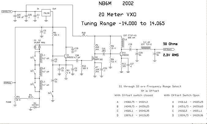
The frequency ranges shown were those obtained in the shack at NB6M with a
pair of 14.060 crystals. Performance with one of the parallel crystals
replaced by the "control" crystal in the judging at Pacificon was very
close to the same.
Here is the circuit of a practical 20 Meter VXO, with one tuning range,
14000.5 to 14044.0 KHz, and with
RIT. This very stable VXO was used as the heart of a 10 Meter Direct
Conversion transceiver.

There is no pulling of the VXO at all on transmit, no chirp, and no drift.
However, if this VXO is to be used in a 20 Meter transceiver, the
VXO, with its RIT and buffer amplifier circuits, would need to be totally
shielded.
The same buffer amp that was used in the 20 Meter VXO Contest entry could
be used to follow this VXO. It is designed to put out a little over 2 Volts
RMS into a 50 Ohm load.
Here is the circuit for the 40 Meter VXO entry:
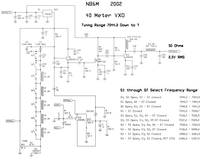
The RIT in this circuit works very nicely, and provides a very useful
amount of offset throughout the tuning range. The judges in the contest
found this VXO's tuning range to be 309 KHz, from 7044 down to 6735 KHz.
Although it pulled further than that, it lost its stability at that point.
This VXO has been used to drive an older, tube type transmitter with good results,
by installing a half-watt, 51 Ohm resistor from the output to ground, inside the
VXO case, so that the buffer amplifier was provided with the proper load.
Here is the circuit for an experimental 80 Meter VXO that uses a pair of 3.579 MHz crystals.
It tunes from 3545 to 3565 KHz, which provides nice coverage of the 3560 KHz QRP calling
frequency.
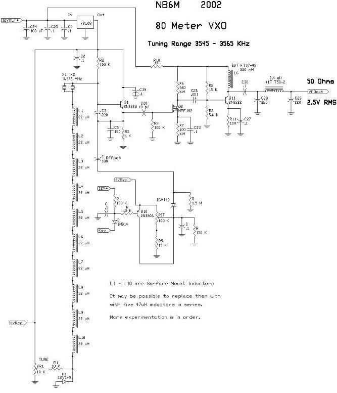 Quite a bit of "leverage" is being used here, in order to pull these color-burst crystals
down enough to cover a nice, 20 KHz, more or less, frequency range around the 80 Meter QRP
frequency of 3560 KHz.
Quite a bit of "leverage" is being used here, in order to pull these color-burst crystals
down enough to cover a nice, 20 KHz, more or less, frequency range around the 80 Meter QRP
frequency of 3560 KHz.
The RIT circuit, with the values shown, does provide a very useful amount
of offset throughout the tuning range. However, more experimentation is
needed, both with the offset capacitor value and the resistor values around the
RIT pot. More info on this VXO will follow as it is developed into a repeatable,
practical circuit.
The results of these experiments, and the experiments of the several others who
have been and are working on VXOs, show that, even in circuits that we have
taken for granted for years, new and different techniques can and do produce
remarkable results. Most of us, myself included, had accepted and were
happy with the idea that a VXO was good for only a few KHz of tuning range.
Who would have thought of being able to build a VXO with a wide enough tuning
range to cover a large portion of the CW band, or of applying RIT to it?
Although most of the very wide tuning ranges of the two VXO Contest entries
described here was wasted, outside our allowed frequencies, and, in fact the
further the VXO is pulled from the crystal frequency, the more non-linear the
tuning is, they do show that very good results can be had if we start with a
pair of crystals on a frequency a few KHz above the upper limit of the desired
tuning range, and then apply similar techniques to those described above in
order to pull the oscillator a reasonable distance.
The good news is that the limits of "a reasonable distance" have changed.
They have increased by a large margin.
The very practical 14 MHz VXO circuit above, which tunes from 14000.5 to
14044 KHz, is a good example of what is an easily repeatable and very useful
VXO circuit.
The thing is, it can easily tune several more KHz below the bottom of the
band, which tells us that if we had a pair of crystals on about 14085 KHz or
so, we could build a stable VXO, with RIT, that would cover the lower 65 KHz
of the band in one tuning range.
Likewise, I believe that a stable VXO, with RIT, could be built that would
tune from 7000 to 7050 KHz, or higher, in one tuning range, if we had a pair
of crystals on about 7070 KHz or so. These ideas are worth pursuing, because
of the frequency stability these VXOs provide and their easy duplication.
Currently, experiments are being made with a wide range VXO using a pair of
7.122 MHz crystals. Initial results have shown that a VXO using a pair of
these crystals can be made to tune from 7094 down to 7000 KHz. Like the 80
Meter VXO shown above, this one needs further refinement, both in the basic
oscillator circuit and in the RIT addition. There will be more on that,
later.
The results described above for each of the VXOs were had when two crystals
of like frequency were paralleled. What can we do with more than two?
Everything I had read about the so-called "Super VXO", using paralleled
crystals, said that two crystals in parallel gave a pretty good gain in tuning
range, but the addition of a third crystal gained nothing more. That was not
what was found when three crystals of like frequency were paralleled here.
More tuning range was available than with two.
The non-linearity of the tuning of the VXO, getting worse the further away from
the actual crystal frequency the oscillator is pulled, would seem to limit
the practicality of a very wide range
VXO. But, what happens if we apply the tuning voltage to the varactor diode
in some non-linear fashion in order to compensate for that?
The point is that many things are left to try and experiment with, and that
is how we learn and how we make our hobby even more enjoyable.
See you on the air.
Enjoy.
Wayne
NB6M
|