The accompanying circuit details should provide anyone who has a small parts
bin with a very useful accessory, allowing the use of smaller, modern crystal
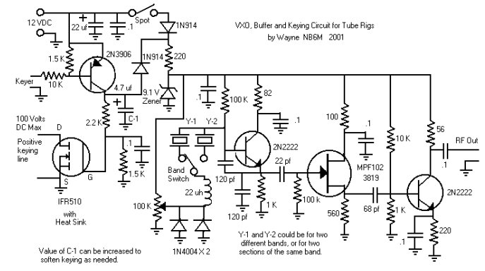
types to control and provide drive for tube rigs. In addition, a Mosfet
switching circuit is included so that an electronic keyer can be used to key
the rig.
I use this VXO, buffer and keying circuit with my old Heathkit DX-40, and
it provides stable operation over about a 4.4 Khz segment of the 40 Meter
band, from 7037.5 to 7041.9 Khz, about 2 Khz of tuning range in the 80 Meter
band, and the keying circuit included allows me to use my Tick keyer even
though there are 90 Volts DC across the key jack in the old rig.
As the feedback capacitors in the oscillator circuit are optimized for the 40
Meter band, the best utilization of the circuit would be on that band, perhaps
with more than one crystal, giving operational capabilities in more than one
segment of the band. The spot switch would be used to spot the oscillator
frequency in the receiver, and then turned off so that the electronic switching
circuit could be taken advantage of to key not only the tube type transmitter
but the oscillator and buffer as well, eliminating any backwave.
With the feedback capacitor values suggested, the circuit will oscillate
quite well with an 80 Meter crystal, and perhaps on other frequency bands
as well, but the oscillator will not start and stabilize quickly enough on
3.5 Mhz to prevent a small amount of chirp when electronic keying of the
oscillator and buffer is utilized. The circuit can be used on 80 Meters, as
is, by leaving the spot switch on during periods of transmission. With the
oscillator running full time, there is no trace of chirp. The circuit can be
optimized for 80, or for other bands than 40, by adjusting the values of the
two, 120 pf feedback capacitors. Simply figure the Xc of the 120 pfs on 40,
and use a capacitance value that would give close to that same amount of
reactance on the band of choice.
I experimented with several values of feedback capacitance between the
approximate value needed for quick starting and stabilization of the
oscillator on 80 Meters, about 240 pf, and the 120 pf values used on 40, in an
attempt to arrive at a value which would give acceptable stability with
electronic keying of the oscillator and buffer as well as the transmitter
on both bands, with no success. I also experimented by installing an additional
PNP switching transistor circuit to turn the oscillator and buffer on slightly
ahead of the transmitter, which made no discernable difference in signal quality.
It may well be that the oscillator circuit, with the values suggested, will
give more than acceptable performance on both 40 and 30 Meters with electronic
keying of the oscillator and buffer as well as the transmitter, but I lack the
30 Meter crystal necessary to make that test. You are welcome to experiment.
Power is turned on and off to the circuit by the very positive means of plugging
in and unplugging the 12 Volt DC power cord. The spot switch is turned on in
order to spot the transmitting frequency in the receiver, and then turned off.
With the spot switch off, the oscillator and buffer are supplied with power when
the key line is grounded and the keying circuit switches on.
The keying circuit takes advantage of the fact that the power Mosfet used, the
ubiquitous IRF510 (hate to use it just for switching, hi), is rated for a
maximum of 100 Volts DC from Drain to Source. A 2N3906 is used to switch the
IRF510 on and off, so that when the key line is grounded, the Mosfet is switched
on, and the transmitter is keyed. The value of C-1 in the accompanying circuit
can be increased if your keying is too hard.
You could try paralleling the crystal used with another one of the same
frequency, and perhaps double the frequency swing of the VXO. However, in
tests I have made with parallel crystals in this circuit, the frequency jumps
around at places in the tuning range, and I have elected to stay with the
smaller tuning range of one crystal. Again, you are welcome to experiment.
The complete circuit can be very easily built into an Altoids tin. The unit
as drawn requires 12 Volts DC, from either a battery pack or power supply.
A 9.1 Volt Zener diode regulates the voltage supplied to the VXO and buffer
amplifier, and the keying circuit operates directly from 12 Volts. Any of a
number of transistor types could be substituted. For the NPN bipolar
transistors, 2N2222, 2N3904, 2N4401, or similar types can be used. For the
FET, MPF102, 2N3819, J310, 2N4416, or similar will work. If you don't have
the exact resistance or capacitance specified, something close will probably
do just fine. For the bypass capacitors, anything from .01s to .33s should
work.
Enjoy.
Wayne NB6M
Copyright 2001
|