By Wayne McFee NB6M
© 2005
OVERVIEW
The SM40 transceiver, available in the near future from the NorCal QRP Club,
is a very nice little surface mount project, designed by Song Kang, WA6AYQ.
Builders will find that Song has designed the rig in such a way that there
are no toroid coils to wind, that the receiver has a very nice, clean sound
and plenty of sensitivity and selectivity, and that the transmitter puts out
about 1.2 Watts.
As designed, the rig has about a 13 KHz tuning range, from about 7030 to 7043
KHz. While this tuning range does cover the main area of interest for QRPers
in the 40 Meter band, I wanted more band coverage, and decided to see what
could be done to both increase the tuning range of the VXO LO and maintain good
coverage of the area of the band centered around 7040 KHz.
Drawing from my previous experiments with extending the range of VXOs, outlined
in the article entitled "How Low Can We Go With A VXO?", and going forward from
that knowledge base with several new experiments, this modification was
developed. It gave the modified SM40 a tuning range of 33 KHz, tuning from
7020 through 7053 KHz.
This modification extended the original upper limit of the tuning range, as
well as the lower limit, giving more coverage above the 7040 KHz QRP calling
frequency as well as below.
These results are accomplished without switching networks, allowing the
operator to tune from well above 7040 KHz to well below it, into the upper
edge of the Extra Class CW band, in one turn of the tune pot.
Although more extended frequency range could have been accomplished, this
Mod was designed to allow the user to retain the original tune pot supplied
with the kit, and still have coverage of a more useful portion of the CW band.
SPECIAL TOOLS NEEDED
If the rig has already been built, two, low-wattage soldering irons will be
needed. If not, one will be sufficient.
Silver-content solder
Magnifier or large, lighted, supported magnifying glass
Tweezers, spring loaded needle-nosed pliers, or spring loaded, clamp type heat
sinks, for placing and holding parts while soldering.
PARTS NEEDED
If you choose to do the mod, you will need five parts. Surface mount parts
were used in the trial modification, as follows:
1205 package, 4.7 uH inductors - 2
MMBT3904 Transistor - 1
10K 0805 package Resistors - 2
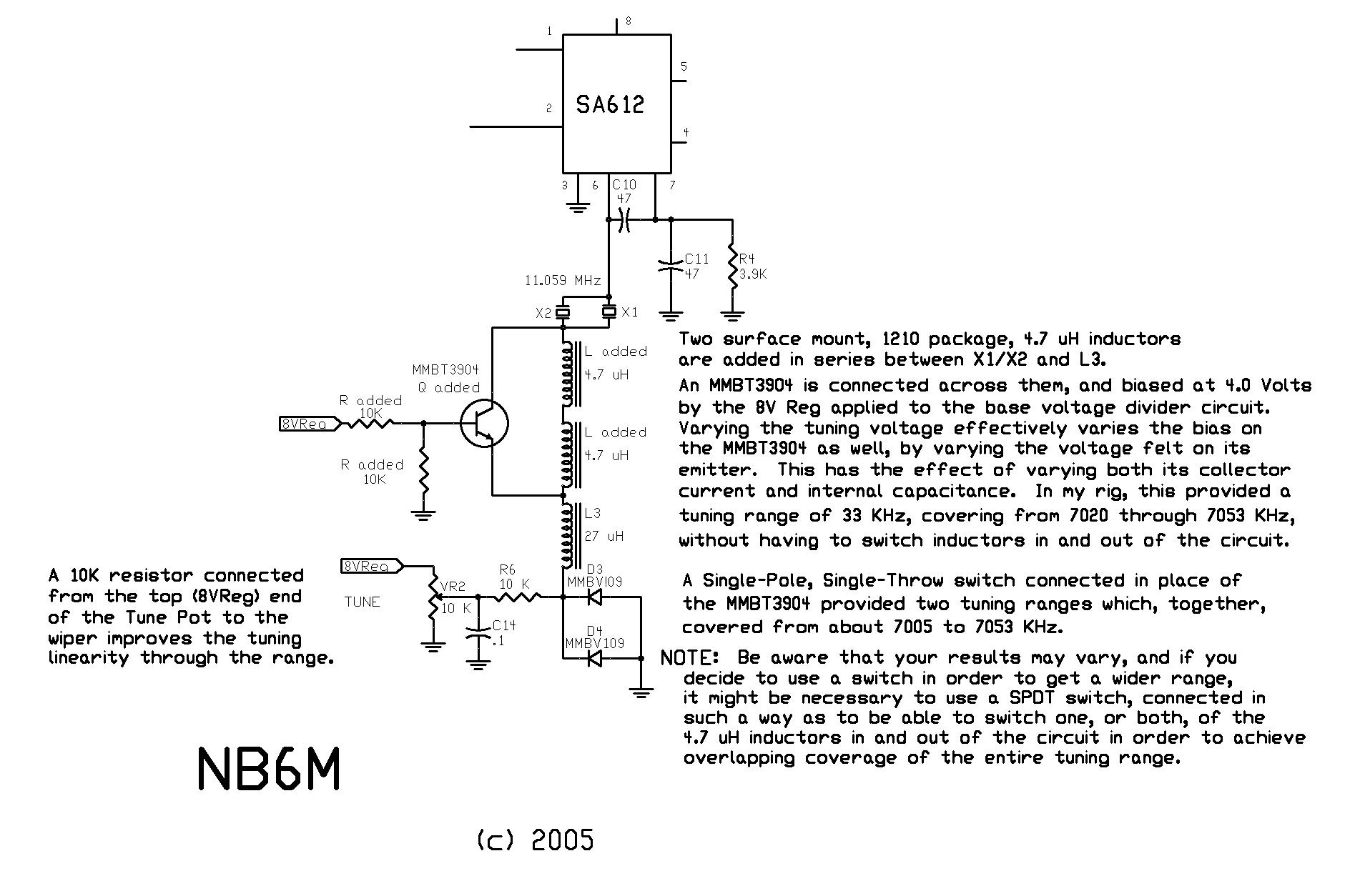
SCHEMATIC OF MODIFIED SM40 VXO
MODIFICATION METHOD
Please understand that, since I built my SM40 without an etched PC board,
using the Ugly Style of building, I don't have the kit version of the PC
board to make reference to in outlining this mod. Therefore, you will have
to use a little imagination on your own to locate the points I refer to here.
There are five parts required to complete the mod, connected as shown in the
above schematic drawing.
In addition to the five parts that are installed, one part is removed, the 22K
resistor that bridges the 27 uH inductor in the VXO circuit.
If you have not yet built the kit, the best preparation for this mod is to
retain, and not install, both the 27 uH inductor and the 22 K resistor that
connect between the crystals and tuning diodes in the VXO circuit.
If you have already built the kit, then you will have to use a pair of
low-wattage soldering irons to remove those two parts.
Next, determine, either visually or with an ohm meter which of the pads for
the 27 uH inductor connects to the cathodes of the tuning diodes.
Then, solder one end of the 27 uH inductor to that pad, with the inductor
standing up vertical to the surface of the PC board. If you have not yet
installed this inductor, it will help to lightly tin the pad it is to be
soldered to, the one that connects to the cathodes of the tuning diodes, and
lightly tin one end connection of the inductor.
As you will see, if you stand the inductor up on the pad, and place the
soldering iron at the junction of what is normally the bottom of the inductor's
end contact and the pad it is to be soldered to, the part can easily be
fastened in place.
Now, at this point, it would be good to gain an understanding of how to
connect the next few parts.
Have a look at the drawing below:
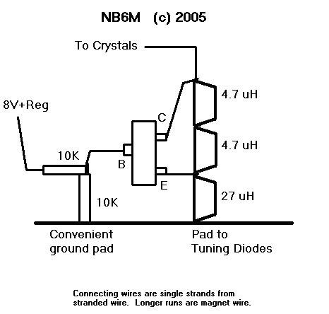
This drawing is not to scale, but does show how the five added parts are
connected to the 27 uH inductor we have now soldered in place, vertical to
the board, with its lower pad soldered to the pad that connects to the
tuning diodes.
What we are going to do is to strip the insulation from about an inch of some
insulated, stranded wire, of a relatively small size, perhaps #18 or so, and
separate out just one strand, by bending it out at a ninety degree angle to
the other strands.
It helps to leave the strand attached, at the moment, as the unstripped wire
makes a nice handle.
Tin the upper contact of the 27 uH inductor, tin the end of the single strand
of wire, and solder the two together.
Now cut the single strand of wire, leaving about an inch of pigtail.
Next, we are going to solder one end of a 4.7 uH inductor on top of the single
strand of wire and upper end of the 27 uH inductor, as shown in the drawing.
Tin one end contact of the 4.7 uH inductor and solder it in place. Be sure to
hold the 4.7 uH inductor steady while the solder cools enough to solidify.
Now tin the upper end of that 4.7 uH inductor, tin one end of the second
4.7 uH inductor, and solder the second inductor to the top of the first 4.7 uH
inductor, as shown in the drawing.
Next, separate out one more single strand of wire, tin the end, tin the upper
contact of the second 4.7 uH inductor, and solder the end of the single strand
of wire to it.
Cut the single strand of wire, leaving about an inch of pigtail.
Now, if you orient the MMBT3904 so that its identifying printed markings are
facing you, and the single contact is to the left, the connections will be as
they are shown in the drawing.
Next, you will want to cut the two pigtails of single stranded wire to a length
of about 3/8th of an inch.
Lightly tin all three contacts of the transistor.
Solder the Emitter contact to the wire going to the junction of the 27 uH and
4.7 uH inductors. Solder the Collector to the wire going to the top of the
upper 4.7 uH inductor.
Now, identify a nearby, convenient ground pad.
Tin the end contact of one 10K resistor, and solder it, in an upright, vertical
position, to the convenient ground pad. Then tin the upper contact of the
resistor.
If the distance between the upper end of the 10K resistor and the base of the
MMBT3904 is short, a bare, single strand of wire can be used to connect them.
If the distance is greater, or there is danger of the lead shorting out, then
use small magnet wire, perhaps #30, cut to appropriate length.
Carefully scrape 1/8th inch of insulation off both ends of the magnet wire, tin
the ends, and solder one end to the top of the 10K resistor. Solder the other
end to the base of the MMBT3904
Now, tin one end of the other 10K resistor, and solder that end to the junction
of the first 10K resistor and the wire leading to the base of the MMBT3904.
Then tin the free end of the second 10K resistor.
Next, identify a convenient pad from which to draw 8 Volts regulated. This
could even come from the top end of the tune pot, if necessary.
You will want to use #30 magnet wire, or VERY small stranded, insulated wire
for this lead, cutting it to appropriate length, scraping the insulation from
the ends, and soldering one end to the pad or contact for 8 Volts Regulated,
the other to the free end of the second 10K resistor.
Lastly, we will connect the top end of the top 4.7 uH inductor, and its lead
going to the collector of the MMBT3904, to the PC board pad that was intended
to connect one end of the 27uH inductor with the twin VXO crystals.
If there is no danger of this lead shorting out, then a single strand of bare
wire can be used. Or, use either #30 magnet wire or very small gauge
stranded, insulated wire.
Once that last connection is made, your mod is complete.
Your results may vary, and I would expect they would to some small extent.
But, you should find that your tuning range is significantly extended, and
in a very good way, both above and below 7040 KHz.
There is one further step you may wish to make. If you connect a 10K resistor
between the top, 8V+ Regulated end of the tune pot, and its wiper, that will
make the tuning across the entire tuning range more linear.
CLOSING THOUGHTS
It is always fun and exciting pushing the envelope on any design, applying new
and different techniques so as to achieve particular goals, such as applying
RIT to VXO circuits and, in this case, using the characteristics of a bipolar
transistor, in combination with added inductance, to easily and simply extend
the frequency of a VXO in both directions without having to resort to switching
methods.
The Ugly Style building method involved in doing this mod may seem daunting at
first. But really, it is straightforward and easy. Try it. The results are
well worth the effort.
Enjoy,
Wayne NB6M
© 2005 NB6M