The best part about these paddles is that you can make them yourself in just
a couple of hours or so, start to finish. They are made from readily
available materials, and cost almost nothing to build.
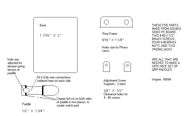
All that is required are some scraps of double sided PC board material, a
piece of single sided PC board material for the base, measuring 1 7/16" by
2", two optional phono jacks, two short pieces of hookup wire, four 4-40
brass nuts, and two 4-40 by 1/2" long brass screws. One more 4-40 brass
screw, one inch long, is used to position the adjustment screw supports for
soldering, and is then put back in the junk box.
The base could be made out of double sided PC board, if you want. The phono
jacks are optional, because you could very well just solder the wires of the
connecting three wire cable directly to the paddle set, which is what I did
when I made my first one of these.
To get an idea of what you are building, have a look at the drawings. You
will see that the whole setup is very simple. The rear frame, paddle, and
two adjustment screw supports are all made out of double sided PC board
material.
The tools you will need are: Hack saw (just the blade will do), file for
rounding and smoothing edges, a small hand (or electric) drill and
appropriate bits, and a low wattage soldering iron and solder. For enlarging
the tension adjustment hole in the paddle, you can use a tapered reamer
(available from Radio Shack) or a small rat-tailed file.
Using the drawings as a guide, first cut out and shape the five parts made
from PC board material. Note that it will be far easier to drill the holes
for phono jacks in the rear frame, the initial hole for tension adjustment in
the paddle, and the holes for the adjustment screws BEFORE cutting the
relatively small pieces from the board. First, outline their shapes in the
material, drill the appropriate holes, and then cut the pieces from the board.
Then, use the file to round corners and smooth the edges of the pieces.
As noted, I soldered one 4-40 brass nut to one side of each of the adjustment
screw supports, in order to provide the threads for the screws to fit into.
You could simply drill and tap (with a 4-40 tap) the PC board material and
use just the lock nuts. However, in the interest of strength and durability,
I recommend soldering a nut to each support.
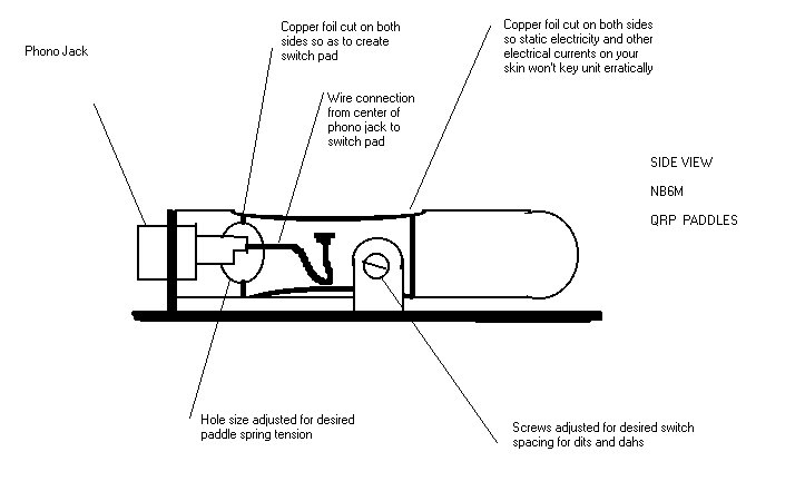
Note that the copper foil is cut in two places on each side of the paddle.
This can be done with either the edge of a small file or with the hack saw.
Cut just enough to be sure you have seperated the copper foil nicely. What
you are doing is creating the switch contact pads for the Dit and Dah side of
the paddle. It is necessary to cut the foil in two places on each side of
the paddle, as shown in the drawings, so that static electricity and other
stray electrical currents from your skin won't cause erratic keying.
The tension adjustment hole in the paddle is enlarged (thereby removing
material from the paddle itself) to provide whatever paddle spring tension
you desire. This is done before the phono jacks and connecting wires to the
switch pads are installed, and AFTER the paddle set itself is soldered
together and the adjustment screws are installed and adjusted for whatever
switch gap feels good to you. So, initially, cut about a 1/8" hole.
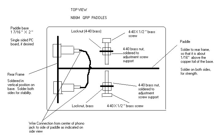
The assembly procedure is as follows:
First, set the rear frame in place, centered and about a quarter inch in from
one end of the base, and tack solder one lower edge of the rear frame to the
base. Check visually for proper placement and that the rear frame is
perpendicular to the base. Heat the solder tack, move the rear frame as
necessary with a finger, and let the solder tack cool. Then tack the other
side before running a bead of solder all along each lower side of the rear
frame.
When you are running a bead of solder between two surfaces which are at 90
degree angles, the trick is to prop the unit up so that the two surfaces form
a V, with the apex at the bottom and the two sides about 45 degrees from the
vertical. This way, the melted solder will run quite nicely along both sides
of the joint, and form a very strong and nice looking connection.
Next, solder one 4-40 nut to one side of each adjustment screw support. The
trick to doing this is to screw the nut onto a screw, put the end of the
screw through the hole in the support, rest the support in a horizontal
position, heat the nut and its adjoining copper foil, and wick the solder
underneath the nut. Once the nut has been soldered in place, and the unit
has cooled, simply unscrew the screw from the nut, and do the same operation
on the other support.
Then, position the two adjustment screw supports on the paddle base, and
solder them into place. The trick to positioning them is to screw the one
inch long 4-40 brass screw through both supports, leaving about a 3/8" space
between the two soldered on nuts, which should be on the inside of each
support, facing each other. Use the paddle as a guide to how far away from
the rear frame to position the supports. The front edge of the supports
should be about even with the foil cuts seperating the touched portion of the
paddle from the switch pads. The far end of the paddle, with the tension
hole in it, will butt up against the rear frame, and, AFTER the adjustment
screw supports are soldered in place and the one inch screw removed, it will
be installed permanently.
The adjustment screw supports should be soldered along both lower sides of
each support. Again, tack solder one side, then the other, and then run a
bead of solder along the lower edge of each. this will insure that they
don't move during the soldering process.
Next, remove the one inch screw from the adjustment screw supports, install
the two lock nuts, one on each screw, running the lock nuts right up to the
screw heads, and screw the adjustment screws into their respective supports.
Leave enough space between the two to fit the paddle between them.
Place the paddle in position between the two adjustment screws and butted up
against the rear frame. The lower edge of the paddle should be at least
1/16" above the surface of the base.
Finger tighten the two adjustment screws against the paddle, which will hold
the paddle pretty well in position while you then tack solder each side of
the paddle against the rear frame and then run a bead of solder along the
edge of each side of the paddle where it butts against the rear frame.
Now, loosen the two adjustment screws slightly, and adjust them for whatever
switch gap feels good to you. Tighten the lock nuts to maintain that gap.
Before installing the two phono jacks and the two short pieces of hookup wire
that connect from the center of each to their respective switch pads, open up
the tension hole as desired, removing material a little at a time, until you
have whatever paddle spring tension feels good to you. Remember that you can
always remove more material. It is hard to put it back.
When you have the paddle spring tension set to your liking, install the two
phono jacks, and solder the two short pieces of hookup wire to the center
connections of each and to their respective switch pads. Remember to leave a
small amount of slack in each wire so that the paddle can move easily.
You will need a three wire cable (or two shielded audio cables with a stereo
miniature phone plug installed on one end and two phono plugs on the other)
to run from the paddle set to your keyer or rig. I used a pair of shielded
audio cables, cut the phono plugs from one end of each and installed a stereo
miniature phone plug, soldering the shield of each audio cable to the ground
connection of the plug, one center wire to the ring connection and one to the
tip connection of the plug.
Before you install the stereo plug, cut several short (3/16") lengths of the
outer insulation from some scrap RG-58 (or 59 or whatever you have) and slip
these over the two audio cables, spacing them about every three inches.
Makes great cable ties and looks good also, with black audio cables.
That's all there is to it. You now have a very portable small, light, and
best of all, cheap set of paddles.
I operate them by either holding the paddle set in the palm of one hand and
operating the paddle with the thumb and forefinger of the other, or by
holding the paddle set down on a tabletop with my middle finger placed over
the junction of paddle and rear frame, and the tip of my forefinger placed
next to the adjustment screw support on the near side of the paddle frame,
which leaves plenty of room to operate the paddle with the thumb and
forefinger of the other hand.
Enjoy,
|
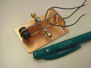
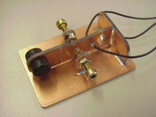
NB6M's Paddles built by Carel Mulder, PA0CMU
|
As a QRP enthusiast and home brewer I often surf the web for small and
easy to build paddles or interesting schematics. I found the
article from NB6M on the Norcal page.
Although I normally use a Bencher BY-1 iambic paddle, the construction of this key
was so easy that I immediately decided to build one because the BY-1 is too
expensive to use during field work.
I used some double-sided printed circuit board, fret saw and file to construct
the paddle within 2 hours. Dimensions are as given by NB6M.
I didn't use plugs but soldered 3 pieces of wire to test and adjust the
paddle. Screws 4-40 are not(?) available in the Netherlands so I
used metric M3 screws.
 I noticed that there is a difference in the resistance you feel while
moving the lever to the DOT or the DASH side, especially when the contact
space is minimal and the finger pressure is low. This is caused by the
tension in the solder at the fixing point of the lever.
I noticed that there is a difference in the resistance you feel while
moving the lever to the DOT or the DASH side, especially when the contact
space is minimal and the finger pressure is low. This is caused by the
tension in the solder at the fixing point of the lever.
I'm not used to single-lever paddles, so the cw code was not faultless
during my first QSO. I placed a rubber nut on each side of
the lever to make it feel better.
Using this type of construction as a foundation I'll make a double-lever paddle.
Adjustment of the contact-distance in relation to the tension in the
material when using this design (both contacts are between the two
levers!) is the bottleneck up to now.
73 de Carel, PA0CMU
|